Project Overview
This case study explains how to plan and install IP68-rated RGBW LED strips for a steam room, sauna, or high-humidity ceiling installation where the strips are recessed in aluminium profiles. The setup uses a corner-friendly layout without soldering at the bends, ensuring maximum reliability in wet conditions.
Key Installation Concept – Corner Lighting Without Soldering
One of the main challenges with IP68 LED strips is creating L-shaped corners without compromising the waterproof seal. Instead of bending or soldering inside the corner (which can be extremely difficult and shorten the strip’s life), the method here is:
-
Cut two separate strips to meet at the corner in an “L” shape.
-
Power each strip from its own end, ensuring both receive the same control signal and voltage.
-
Avoid making any direct connection between the two strips at the corner.
This avoids waterproofing issues at the bend and ensures the installation meets IP68 standards.
Cut Length Planning – Why 10cm Increments Matter
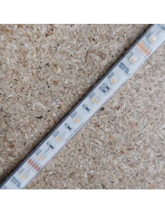
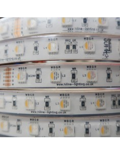
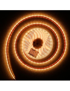
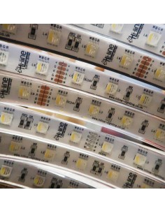
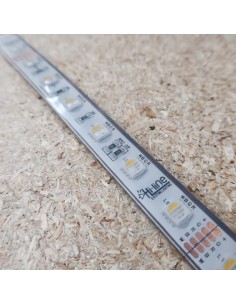
All LED strips have fixed cut points. For this specific RGBW IP68 strip (HL-24VRGBWW-IP68-PU), each cut point is every 10 cm (6 LEDs).
Cutting anywhere else will damage the copper PCB and break the circuit. Therefore, all section measurements are rounded down to the nearest 10 cm to maintain function and safety.
Equipment Used – References Only
-
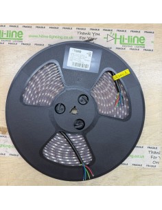
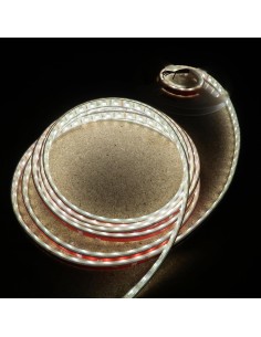
HL-24VRGBWW-IP68-PU – 5m RGBW IP68 LED strip roll
-
HL-300W-24V-IP67-5Y – 300W 24V IP67 LED driver
-
HL-V4-WPS – Waterproof 4ch RGBW controller
-
HL-R8-1 – RGBW remote control
-
HL-5PMC-IP68-508 – 5-pin IP68 connector (for strip tail extensions)
-
HL-3PMC-IP68-508 – 3-pin IP68 connector (for driver input/output)
-
HL-LS-ESP12MM – End caps for 12mm LED strip
-
HL-706TM-45G – LED-safe silicone sealant
End Sealing & Waterproofing
Any freshly cut end must be resealed with:
⚠ Important: Only use LED-safe silicone. General-purpose silicone can cause short circuits or PCB corrosion, especially in steam rooms and humid areas.
Handling & Installation Notes
-
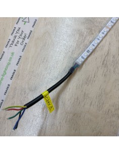
Handle factory pre-soldered tails with care. Each tail contains 5 solder points on a micro PCB pad, so avoid twisting or pulling.
-
Use proper IP68 connectors to extend tails safely to the controller.
-
Ensure installation is done by a qualified professional, following IEE wiring regulations.
-
Always plan driver placement to allow safe cable runs and minimal voltage drop.
Learning Points for Similar Projects
-
IP68 in Corners: Always cut and power strips separately rather than trying to bend or solder at a corner.
-
Factory Seals Last Longer: Avoid making your own joins unless absolutely necessary.
-
Plan Cuts in 10cm Steps: Respect the strip’s fixed cut points to maintain functionality.
-
Installer Responsibility: Product recommendations are based on given measurements; final design must be verified by the installer.