What this article is for
Consultants and installers often specify “LED ribbon” and a connector pack as if those two items were interchangeable. They are not. The cable gauge, the number of cores, the connector housing, the strip width and the electrical load all have to match. Get one of those wrong and the site shows it as colour shift, a hot joint, a dim far end, or a controller that browns out when every channel is full.
This note covers three things that belong on the drawing, not only in a conversation on site: solderless connectors, the common core on 3- to 6-wire tape, and voltage drop. The same arithmetic applies to tunable white (CCT), RGB, RGBW and RGB+CCT. It is written as general guidance for 12 V and 24 V constant-voltage LED strip. Hi-Line supplies the parts; a qualified person still has to size the run.
Connectors are not universal
A 3-pin, 5-pin or 6-pin clip is made for a specific strip width, a specific pad layout, and a specific wire size. It will not sit on every ribbon in the range.
Check all three before you order, and test-fit before you commit a run:
- Poles — 3-pin for CCT, 4-pin for RGB, 5-pin for RGBW, 6-pin for RGB+CCT. The wrong pole count will not land on every pad.
- Conductor size the housing will actually grip — commonly 24 AWG, 22 AWG or 20 AWG. 24 AWG is frequent on compact clips. Those housings can be too small even for 22 AWG, just as many 22 AWG housings will not take 20 AWG. Forcing a thicker core distorts the contact or splits the shell.
- Strip width and copper pads — a 10 mm clip will not seat on 8 mm or 12 mm tape, even if the gauge is correct. COB and SMD pads are not the same shape.
Listing a connector next to a cable on the shop is not a guarantee of fit. Read the connector page, then try one joint. If the housing will not take the cable, solder, or change the gauge. The installer decides on the job; the specification should name the gauge and the connector, not just “tails”.
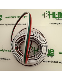
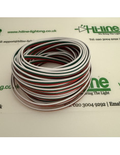
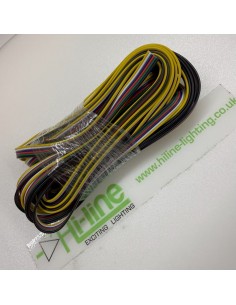
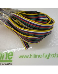
We stock more than one 3-core and multi-core ribbon for that reason. 22 AWG 3-core (HL-3C-AWG22-10M) is the thinner CCT companion to 20 AWG 3-core (HL-3C-AWG20-10M). The same split exists on 5-core RGBW and 6-core RGB+CCT. 20 AWG is usually the sounder electrical choice on a longer or heavier feed — if the connector will accept it.
The common core — 3, 4, 5 and 6 wires
This is the point customers ask about most often, and it is not limited to 3-core tunable white.
Most constant-voltage colour-changing tape is common-anode: one shared positive and a return for each channel. The colour cores only ever carry their own channel. The shared positive carries the whole strip when every channel is on.
| Cores |
Typical strip |
What the common core carries (all channels full) |
| 3 |
Tunable white / CCT |
Warm white + cool white |
| 4 |
RGB |
Red + green + blue |
| 5 |
RGBW |
Red + green + blue + white |
| 6 |
RGB + CCT |
Red + green + blue + warm white + cool white |
Adding cores does not increase the capacity of the common conductor. A 6-core ribbon still has one shared positive. That one wire is the bottleneck.
Worked example, using a 14.4 W/m 24 V strip, 5 metres, every channel fully on — CCT, RGBW or RGB+CCT:
- Total load: 14.4 W/m × 5 m = 72 W
- Current at 24 V: 72 W ÷ 24 V = 3 A in the common core
Warm white and cool white (or red, green and blue) may each be drawing less at a given colour mix. That does not give you spare capacity on the cable. You cannot run extra length because one channel looks lightly loaded. The common conductor is already carrying the combined current, and that is what limits the run.
If the same 5 m is 24 W/m, the common core is 5 A at 24 V. At 12 V the current doubles for the same watts: 72 W is 6 A on the common. Size against that combined figure, not against one colour wire, and not against a “typical” scene.
The same rule sits on the driver. All channels on is the load. That is the subject of our 24 V RGBW PWM driver-sizing note and the RGBW strip wattage article.
Voltage drop
Copper has resistance. The longer the tail and the thinner the core, the more voltage you lose before the first LED. On a colour-changing strip the drop on the common is the one that hurts: every channel shares it. The far end runs dimmer, whites go off-colour, and RGB mixes shift. A controller can also brown out if the voltage at its input has already fallen.
22 AWG and 24 AWG have less copper than 20 AWG. They exist so that compact connectors can grip the wire. They are not a 10 metre feeder for a high-wattage tape. Work out the drop for the actual length, voltage and watts. If the numbers are tight: shorten the tail, inject power along the strip (both ends, or a mid feed), step up to 20 AWG where the housing allows, or split the run onto more than one feed.
Do not treat a 10 m roll as a 10 m supply cable. The roll is stock. The usable length is whatever the calculation supports with an acceptable drop at full load.
A solderless connector is often the highest-resistance joint on the run. A clip that is the wrong gauge, not fully closed, or on oxidised pads will heat first. If the current is high, solder the joint.
A 10 m roll is not a 10 m feed
Many solderless clips only grip 24 AWG or 26 AWG. That is why a 10 m coil of thin ribbon looks like the obvious answer: the clip fits, so the whole 10 m goes to the strip. The housing may close. The copper will not carry a heavy load over that length.
Worked example — 75 W at 24 V, fed over 10 m one-way (20 m of copper there and back). Figures are typical copper; treat them as an illustration, not a design certificate.
- Current: 75 W ÷ 24 V ≈ 3.1 A.
- 26 AWG (~0.13 mm²) loses around a third of the supply on that round trip — roughly 8 V. The strip sees about 16 V instead of 24 V. The cable also turns a large part of the 75 W into heat.
- 24 AWG is a little thicker and still far too thin for 10 m at this load (drop still around one fifth of the supply).
The 10 m on the shop is the coil we sell. It is not permission to run 10 m of that gauge at 75 W. Ribbon is only the right feeder when the length, voltage and watts have been calculated. If those numbers are not on the drawing, do not guess with 24 AWG or 26 AWG.
When the clip will only take thin wire
Keep the thin piece very short. A 10–15 cm tail of 24 AWG into the clip (26 AWG only if that housing will not take 24 AWG) is electrically small at 3 A — a fraction of a volt. Join that tail, properly, to a calculated feeder for the rest of the run. At 75 W over 10 m that feeder is typically 1.5 mm² or 2.5 mm² copper, not another 10 m of LED ribbon.
The joint between the tail and the feeder must be a real termination (solder and sleeve, or a proper connector). Twist and tape will fail. Strain-relieve the thin tail so it cannot be pulled. Prefer a clip that already takes 22 AWG or 20 AWG when the current is this high; several of ours do. Split the load (feed both ends of the strip) if you can, or put the 24 V driver next to the tape and keep the long run on the mains side.
Our 10 m 22 AWG and 20 AWG ribbons are for tails and for matching the connector. They are not automatically the right 10 m feeder for 75 W. Work the numbers, or have a qualified installer do it.
What the consultant should put on the drawing
“LED tape and cable” is not a specification. The pack that goes to site should name, at least:
- strip watts per metre, voltage (12 V or 24 V), IP rating and width
- number of cores and whether the tape is common-anode
- cable gauge (24 / 22 / 20 AWG) and maximum tail length
- connector model, or an instruction to solder
- power-injection points and how the common is doubled or not
- driver VA with spare capacity, all channels on
- the full-load current in the common core, in amps, written next to the run
If those figures are missing, the installer is left to guess. Guessing is how a 5 m 14.4 W/m CCT run becomes 8 m on 22 AWG into a 24 AWG clip. The drawing should force the arithmetic before the ceiling is closed.
What goes wrong when it is undersized
- Hot common core and hot connector — insulation, housings and pads are the first to suffer. That is a fire and warranty risk, not a dimming quirk.
- Colour and brightness changing along the run — snagging fails, and the client sees it as a product fault.
- Controller or decoder resetting when the scene goes to full white or full RGB+CCT.
- Driver at the limit — short life, thermal cut-out, or a supply that will not restart after a mains dip.
- Rework — opening a finished cornice to inject power or change the cable is many times the cost of specifying the gauge on day one.
None of this is solved by “the other two cores are only carrying half”. They are not the limit. The common core is.
Installer checklist
- Match poles, AWG and strip width on every connector. 24 AWG, 22 AWG and 20 AWG are not interchangeable. Test-fit.
- Size the common core, the connector and the driver for all channels on. Example: 14.4 W/m × 5 m at 24 V is 3 A in the common, whether the tape is 3-core CCT or 6-core RGB+CCT.
- Calculate voltage drop on the actual tail. Inject power or thicken the cable before the far end goes off-colour. Do not run 10 m of 24 AWG or 26 AWG as a 75 W (or similar) feed; if the clip needs thin wire, keep that piece to 10–15 cm and use a calculated feeder for the rest.
- Identify cores with a meter. Jacket colours vary between batches.
- Do not mix common-anode tape with common-cathode controllers.
- Write the amps, the gauge and the injection points on the drawing. Do not leave them as a site decision after the plasterboard is up.
Disclaimer
Hi-Line Lighting supplies products only and does not provide on-site installation, technical consultancy, or a full lighting design service. This article is general guidance for typical 12 V and 24 V constant-voltage LED ribbon. All calculations, wiring, safety checks and regulatory compliance must be carried out and verified by a qualified installer. Incorrect design or installation can cause overheating, equipment damage, or fire.
If you do not have a lighting designer and need help on a larger or more complex project, contact us. We can put you in touch with trusted external partners.
Need help specifying a similar run?
Email [email protected] with the strip watts per metre, voltage, length, number of cores, and whether you intend to use solderless connectors. If you receive an automated reply with a ticket number, keep it. If you do not receive that reply, please call to confirm the message arrived.