sign modules, led signage lighting, backlighting led for signs, lightbox led
LED Lightbox Lighting Explained
Edge-Lit vs Back-Lit Solutions (With a Real CL005 Case Study)
Choosing the correct lighting method for a lightbox or illuminated sign is critical to achieving even illumination, long service life, and a professional finish. One of the most common mistakes we see is trying to force an edge-lit solution into an application where back-lighting is the correct choice.
In this article, we explain:
The two main ways to light a lightbox
When to use edge-lighting and when to use back-lighting
How CL005 LED backlighting modules work
How to size power supplies correctly
A real, practical example using 24 modules
Two Ways to Light a Lightbox
There are two fundamentally different lighting methods used in lightboxes. They are not interchangeable, and choosing the wrong one can result in hot spots, uneven brightness, or visible light fall-off.
1) Edge-Lit Acrylic Panels
Edge-lit systems inject light into the edge of the acrylic, allowing it to travel through the material via internal reflection.
Edge-lighting is typically used when:
The construction depth is very shallow
Edge access is available
A slim, architectural solution is required
Hi-Line Lighting offers a full range of edge-lighting modules suitable for shallow lightboxes and panels. All edge-lighting products can be found here:
Important practical rule: For taller panels, edge-lighting must be balanced, usually by lighting from both the top and the bottom edges. If lighting can only be installed on one edge, uniformity reduces quickly as panel height increases.
2) Back-Lit Lightboxes (CL005)
Back-lit lightboxes place LED modules behind the acrylic, projecting light forward into the lightbox cavity.
For Hi-Line Lighting, the primary product used for this application is:
Back-lit solutions generally require more depth than edge-lit systems, but they offer much greater flexibility when physical constraints prevent correct edge lighting.
Why Back-Lighting Was Used in This Case
In a recent project, edge-lighting was initially considered. However, bottom edge access was not physically possible due to the construction of the lightbox.
Without bottom edge lighting:
Light fall-off through the acrylic would be unavoidable
Uniformity could not be guaranteed
The application would exceed the practical limits of edge-lighting
For this reason, a back-lit solution using CL005 modules was selected instead. This is a very common real-world scenario and highlights why understanding both lighting methods is essential.
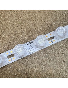
Understanding CL005 LED Backlighting Modules
The CL005 is a 12V constant-voltage LED backlighting module designed specifically for signs and lightboxes.
Key points:
Operating voltage: 12V DC
Power consumption: 1.6W per module
Supplied in linked chains for convenience
Designed to be spread evenly behind the acrylic
Chains, Strings, and Electrical Limits Explained
CL005 modules are supplied in chains of up to 30 modules.
This does not mean you must use all 30 modules.
It means:
30 modules is the maximum allowed in one electrical string for CL005
There is no minimum
Chains can be cut to any required length, even a single module
Examples:
24 modules in one string is perfectly acceptable
15 modules in one string is fine
1 module will still operate correctly
What If More Than 30 Modules Are Needed?
If more than 30 CL005 modules are required, they must be split into multiple electrical strings.
Correct examples:
40 modules as 30 + 10
40 modules as 2 × 20
These strings are then connected in parallel to the same suitably sized power supply.
In simple terms:
Each string has its own positive and negative feed
All strings connect directly back to the PSU
One string must never feed into the next
Physically, modules can still be laid out so they look continuous, but electrically the cable must be cut so each string starts with a fresh feed from the PSU.
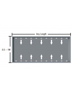
Module Spacing Guidance
For back-printed acrylic with a cavity depth of around 75–80 mm, a sensible starting point is:
100–120 mm centres
Closer spacing improves uniformity. Wider spacing increases the risk of visible hot spots. This guidance must always be confirmed by physical testing, as acrylic type and print density vary.
Power Supply Sizing (Real Example)
Each CL005 module uses 1.6W at 12V.
Real Case Study Example
Modules per lightbox: 24
Total load: 24 × 1.6W = 38.4W
Best practice is to allow at least 20% headroom.
38.4W + 20% ≈ 46–47W
A 60W 12V constant-voltage LED driver is therefore a safe and sensible choice, with one PSU per lightbox:
Using one driver per lightbox keeps wiring simple, avoids long cable runs, and improves long-term reliability.
Oversizing the PSU (Optional for Long Life)
Using a larger PSU, such as 100W, is electrically acceptable and sometimes preferred.
Benefits:
Lower operating temperature
Reduced electrical stress
Improved long-term reliability
This approach is often chosen on projects targeting 10-year operational life or extended warranty expectations. The trade-off is increased physical size and weight.
Connectors and Protection
For IP-rated installations, it is good practice to use suitable connectors on both the PSU input and output.