What the watts per metre mean
On a colour-changing LED strip the watts per metre printed on the listing are the total for the strip, with every channel on together. They are the combined load of the tape. They are the figure to use for the driver, for the common wire, and for the connector.
A 16 W/m RGB + tunable white strip is a 16 watt strip. It is not 16 W of red, plus 16 W of green, plus 16 W of blue, plus 16 W of each white.
The same reading applies across the range:
- Tunable white (CCT) — warm white and cool white together
- RGB — red, green and blue together
- RGBW — red, green, blue and the single white together
- RGB + tunable white — red, green, blue, warm white and cool white together
The arithmetic below is the planning method we use from that stated total. A qualified installer still confirms cable size, protection and voltage drop for the job in front of them.
The common anode carries the whole current
These strips are common-anode. One shared positive feeds the tape, and each colour has its own return. On our reels the shared positive is the black wire.
That black wire carries the sum of the channels. Each colour wire carries only its own channel. At full load the colour returns share the stated watts roughly equally, so each return is about the total divided by the number of channels. The black wire is still carrying all of them.
| Strip |
Channels |
Common anode (black +) |
Each colour return, for planning |
| Tunable white |
2 |
The stated W/m |
About half of the stated W/m |
| RGB |
3 |
The stated W/m |
About one third |
| RGBW |
4 |
The stated W/m |
About one quarter |
| RGB + tunable white |
5 |
The stated W/m |
About one fifth |
Current in amps is watts divided by the supply voltage. A 24 V strip at 16 W/m draws 16 ÷ 24 = 0.67 A per metre on the common anode. The same watts on 12 V draw twice that current.
A scene that uses only one colour loads the common with that one channel, which is lighter. Size the common, the connector and the feed for every channel on. That is the load the black wire has to be able to carry.
Worked example: 16 W/m RGB + tunable white, 24 V
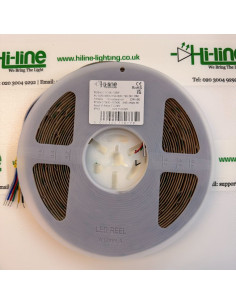
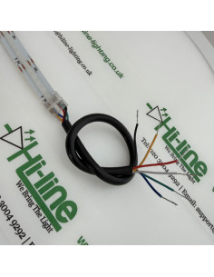
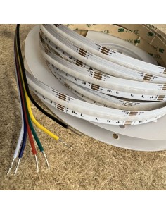
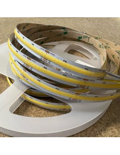
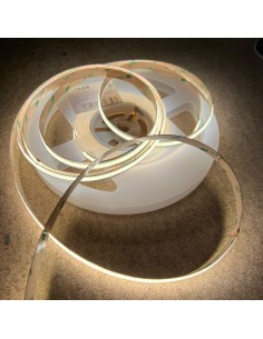
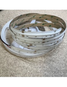
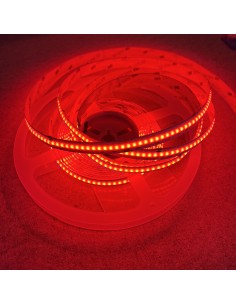
This is HL-COB840RGBTW-R90-IP00-24V (5 m) and the 10 m reel of the same strip. Six wires: black positive, and returns for red, green, blue, warm white and cool white.
- Common anode: 16 W/m ÷ 24 V = 0.67 A per metre on the black wire
- Each colour return: 16 W ÷ 5 channels = 3.2 W per metre, and 3.2 W ÷ 24 V = about 0.13 A per metre
- Whole 5 m reel, all channels on: 80 W, about 3.3 A on the black wire
- Whole 10 m reel, all channels on: 160 W, about 6.7 A on the black wire
Use the same steps on any other strip. Take the stated watts per metre, divide by the voltage for the common-anode current, then divide that current by the number of channels for a planning figure on each return.
A connector is limited by the common pin
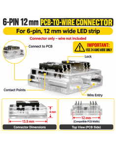
In a 4-pin, 5-pin or 6-pin strip connector, one contact is the common anode. That single contact carries 0.67 A for every metre of a 16 W/m 24 V strip. The colour contacts carry about 0.13 A per metre each. The run is limited by the common contact.
Allowed length on one feed is the contact rating divided by the common-anode current per metre.
- Contact rated 3.5 A: 3.5 ÷ 0.67 ≈ 5 metres of this 16 W/m strip
- Contact rated 5 A: 5 ÷ 0.67 ≈ 7.5 metres of the same strip
Those two ratings are examples of figures printed on connector contacts. Use the rating of the connector on the job. Dividing 3.5 A by the 0.13 A of one colour wire suggests about 27 metres. That number describes a colour contact. The common contact is already at 3.5 A at about 5 metres, so the longer figure cannot be built.
Feeding the strip from both ends splits the current. Each feed then carries about half the reel, and each common pin is sized for the half it actually supplies. Calculate that half. A connector does not become able to carry the whole reel just because the far end also has a tail.
The connector also has to match the strip: pole count, width, and the wire size the housing will grip. That is covered in our note on connectors, the common core and voltage drop.
Long feeds and the size of the common conductor
The same limit applies to a cable run back to the driver. The conductor that continues the black wire has to carry the full common-anode current of the length on that feed, for the whole distance, with an acceptable voltage drop.
The colour cores are sized for their own share. They are the lighter wires. Choosing a cable because “each colour is only 0.13 A per metre” undersizes the one core that carries 0.67 A per metre.
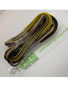
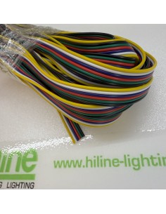
The soldered tails on a reel, and the short ribbon in a clip, are there to make the joint at the strip. They are a short link. A long home-run needs a calculated feeder: cross-section from the current in the common, the length of the run, and the voltage drop you can accept. At 12 V the current is double, so the same feeder has to be thicker again, or shorter.
Our guide to common-core cable and voltage drop works through gauge, a thin tail into a proper feeder, and why a 10 m coil of ribbon is the length we sell rather than permission to feed 10 m at full load.
What should be on the drawing
- Stated watts per metre, as a total, and whether the supply is 12 V or 24 V
- Common-anode current in amps for the length on each feed
- Connector contact rating, and the metres that rating allows on the common pin
- Feeder cross-section and length, sized on the common conductor
- Where power is injected (one end, both ends, or a mid feed)
Driver capacity follows the same total: the watts of the length being fed, with spare for a constant-voltage load. One-colour scenes are not the design case.