What this article is for
Installers and builders often treat every LED tape like the cheap indoor “plug-and-play” type, with clip-on connectors that click onto bare copper. That is fine for many IP20 / IP00 indoor strips. It is the wrong method for a commercial IP67 waterproof strip.
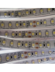
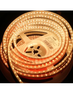
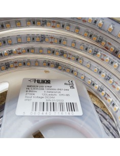
This guide uses Hi-Line’s 12 mm, 24 V, 9.6 W/m SMD3528 IP67 tape as the working example — warm white 2700 K (5 m roll). The same rules apply to the cool white and natural white 4000 K sisters. We have many other IP67 and IP68 tapes; do not order all of them. Match width, voltage, wattage and colour to the job.
The point is not one named site. It is how to cut, power, seal and (only when needed) solder this class of strip so the waterproof sleeve still does its job.
Why clip connectors are the wrong starting point
Home-user IP20 tape is open copper with a paper liner. Clips are designed for that. An IP67 strip is a higher-grade commercial product: the 10 mm PCB sits in a 12 mm silicone sleeve. There is no bare copper waiting for a clip.
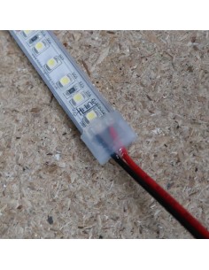
The ready connections are the two factory-soldered tails already on each 5 m roll (about 15 cm of 2-core cable at each end). Those tails are the clean, waterproof way to feed power. If a live end is left open, or a cut is not sealed, water and shorts follow — and that can damage the strip and the driver.
What you get on each 5 m roll
- Two factory tails — one at each end of the roll. That is two ready power feeds, not an unlimited supply of plug-on joints.
- Cut marks every 6 LEDs (50 mm / 5 cm) on this 3528 tape. You cannot cut between the marks.
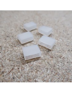
- 12 mm overall width (10 mm PCB). End caps must be the 12 mm size.
- Do not daisy-chain more than 5 m on the copper. Longer runs are powered with 2-core cable back to the driver or controller, not by joining roll after roll in series.
Cutting: one cut versus many cuts
Cut only on a printed mark. A typical example:
- You need one 4 m length from a 5 m roll. Cut at the 4 m mark. You now have 4 m + 1 m.
- The piece that still has a factory tail is ready to power. Seal the new cut end. The 1 m leftover is waste — and that is often faster and cheaper than paying an installer to solder a new join.
| What you do to one 5 m roll |
How many factory tails you still have |
Soldering? |
| Use the roll as 5 m |
Two tails (both ends) |
No — power from a factory tail |
| Cut once (for example 3 m + 2 m, or 4 m + 1 m) |
Each piece still has one factory tail |
No — two ready lengths. Seal the two new cut ends |
| Cut more than once |
Only the two end pieces keep a factory tail. Every middle piece has none |
Yes, if that middle length must be powered |
Long straight runs with few cuts are the easy case: power from the factory tails, cut on the marks, seal the unused ends. That is why many outdoor jobs never need a soldered join at all.
When soldering is actually required
Soldering is not the default. It is the method for a new power join at a cut — typically a middle piece, a custom feed, or a repair. For IP67 that means:
- solder the 2-core cable to the pads on a cut mark
- heat-shrink the joint
- seal and isolate so water cannot enter
That needs an installer with good soldering skill. A poor joint fails, leaks, or overheats. If the builders on site are used only to indoor clip tape, walk them through the factory tails first rather than assuming every cut needs a new connector.
Seal every unused tail and every cut end
Any unused factory tail, and any new cut, must be isolated and sealed. An open live end can short, let water in, and damage the strip or the 24 V driver.
For a cut end on this 12 mm sleeve:
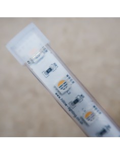
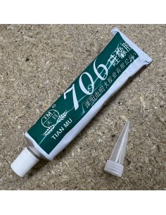
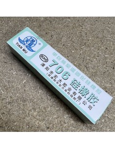
Put a little sealant in the cap and push it onto the cut end. Order the caps and sealant with the strip (or as a later website order if you forgot). Do not expect clip-on indoor connectors to restore IP67.
Example outdoor runs and driver size
This tape is 9.6 W per metre, 24 V. Size the driver with about 20 % headroom. Do not run more than 5 m from one copper feed; each 5 m roll is its own injection point, with 2-core cable back to the supply.
| Typical run |
5 m rolls |
Load |
24 V IP67 driver |
| One full roll |
1 (5 m) |
48 W |
100 W IP67 is comfortable |
| Covered terrace / canopy |
4 (20 m) |
192 W |
300 W IP67 Premium |
| Longer outdoor fascia |
8 (40 m) |
384 W |
500 W IP67 — a 400 W unit is too close once you allow headroom |
Large IP67 drivers have a high inrush at switch-on. On a 500 W class supply that is typically 110–150 A. A HL-S1-SX surge suppressor on the mains side reduces nuisance tripping of breakers and protects dimmers. It is not a substitute for correct driver size.
The driver itself does not have to be dimmable. Brightness is controlled with a PWM controller such as HL-V1-L on the 24 V side. Need more output or a dot-free line? That is a different family — for example the 24 V IP68 COB 10 m 3000 K — not a clip-on version of this 3528 tape.
Installer checklist
- Plan lengths around the 5 m rolls and the two factory tails.
- Cut only on the marks (every 5 cm on this strip).
- Power from the factory tails wherever you can. Accept a short leftover rather than an extra soldered join if labour costs more than the offcut.
- Seal every cut and isolate every unused tail.
- Feed each 5 m (or shorter piece) with its own 2-core run. Do not series-connect beyond 5 m.
- Choose the IP67 24 V driver from the load table, then add the surge suppressor on larger supplies.
- Test dry before you close the location.
What this article is not
It is not a quote for one house, and it is not a promise of on-site help. IP67 widths, cut intervals and wattages differ across the range — always read the product page for the tape you actually ordered. Extra parts (end caps, sealant, another CCT) are ordered on the website as their own lines so packing stays simple and you avoid mixing a half-packed outdoor kit.
Disclaimer
Hi-Line Lighting supplies products only and does not provide on-site installation, technical consultancy, or a full lighting design service. This article is general guidance for typical IP67 24 V LED-strip cutting, sealing and power feed. All calculations, wiring, sealing, safety checks and regulatory compliance must be carried out and verified by a qualified installer. Incorrect design or installation can cause overheating, water ingress, equipment damage, or fire.
If you do not have a lighting designer and need help on a larger or more complex project, contact us. We can put you in touch with trusted external partners.
Need help specifying a similar outdoor run?
Email [email protected] with the total metres, CCT (2700 K / 4000 K / cool white), indoor vs outdoor, and whether you need dimming. If you receive an automated reply with a ticket number, keep it. If you do not receive that reply, please call to confirm the message arrived.