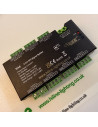
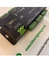
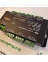
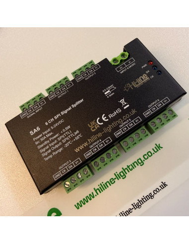
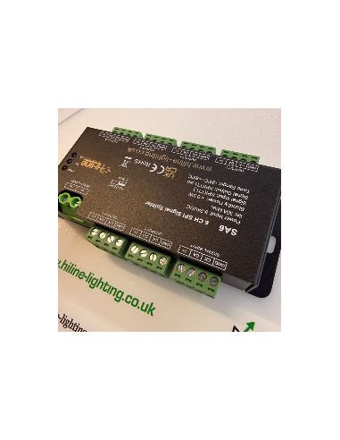
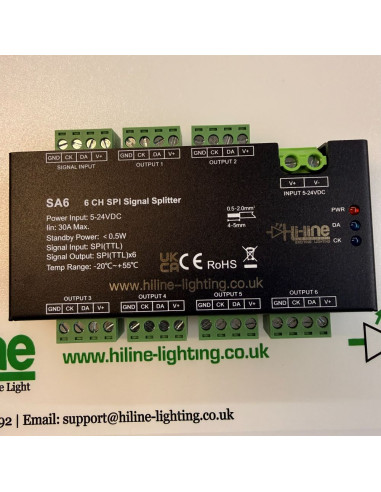
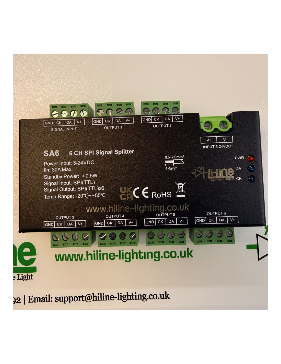
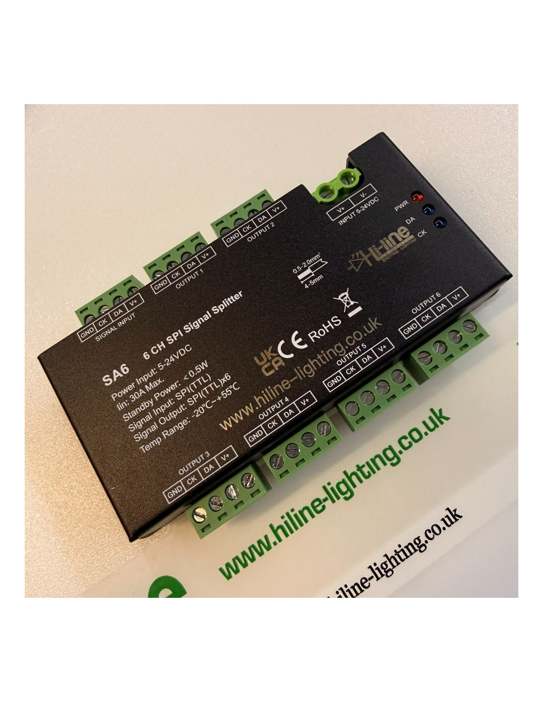
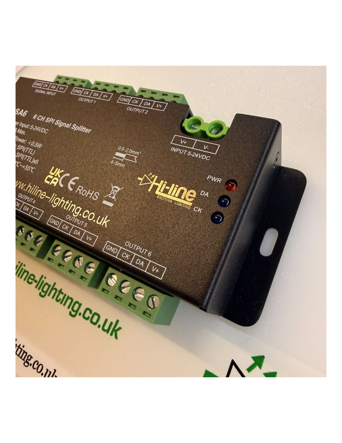
6-Way SPI Signal Splitter & Buffer for Addressable LED Strips (5–24V)
The SA6-SPI is a professional SPI (pixel) signal splitter and buffer designed for use with addressable / digital LED strips such as RGB or RGBW pixel products operating on 5V, 12V, or 24V systems.
It is used to duplicate and stabilise a single SPI data signal, allowing one controller output to drive multiple LED strip runs reliably, with clean signal integrity and consistent performance.
What this product does
The SA6-SPI accepts one SPI (TTL) signal input and provides six fully buffered SPI outputs.
Each output carries:
This means:
-
All connected LED strips display the same effect
-
Pixel effects are repeated / mirrored, not extended
-
Each output starts from pixel 1
This behaviour is intentional and is how most architectural pixel lighting installations are designed.
Important clarification – not a pixel mapping device
This product is not a pixel mapping controller.
It does not:
-
Create one long continuous pixel run across multiple outputs
-
Offset pixel addressing per output
-
Extend pixel numbering beyond the controller setting
If a single continuous pixel effect is required, LED strips must be daisy-chained in series, or a network-based pixel controller with mapping capability must be used.
Typical and recommended use
A very common setup using 60 pixels per metre LED strip:
-
5m strip = 300 pixels
-
Controller set to 300 pixels
-
SA6-SPI feeds multiple 5m strips from separate outputs
-
The same effect repeats on each strip
This method is widely used for:
It offers excellent reliability, simple wiring, and easy commissioning.
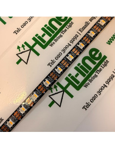
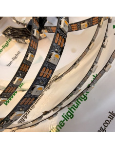
Supported SPI LED strip types
The SA6-SPI supports common SPI (TTL) addressable LED protocols, including:
Depending on LED type:
-
Single-wire SPI: each output can drive up to two LED strips
-
Two-wire SPI: each output drives one LED strip
-
One unit can support up to 12 strips (single-wire) or 6 strips (two-wire)
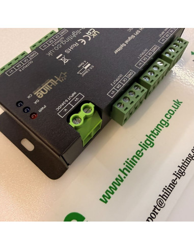
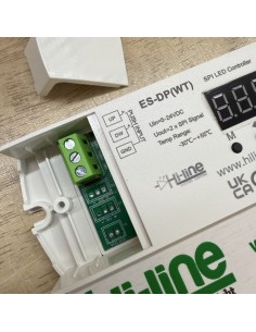
Power wiring – very important
This unit distributes signal only, not power.
When using individual power supplies per LED strip (common with high-power pixel installations):
This is essential for correct SPI data reference and stable operation.
Positive outputs (5V / 12V / 24V) must remain completely separate.
Do not connect positive outputs of different power supplies together, as this can cause damage or failure.
In simple terms:
Cable length guidance (signal side)
From each SA6-SPI output to the first LED pixel:
For best results:
-
Use twisted pair cable for DATA and GND
-
Keep signal cables away from mains and driver outputs
-
Ensure all grounds are common
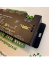
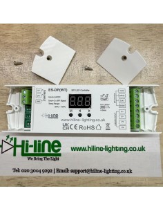
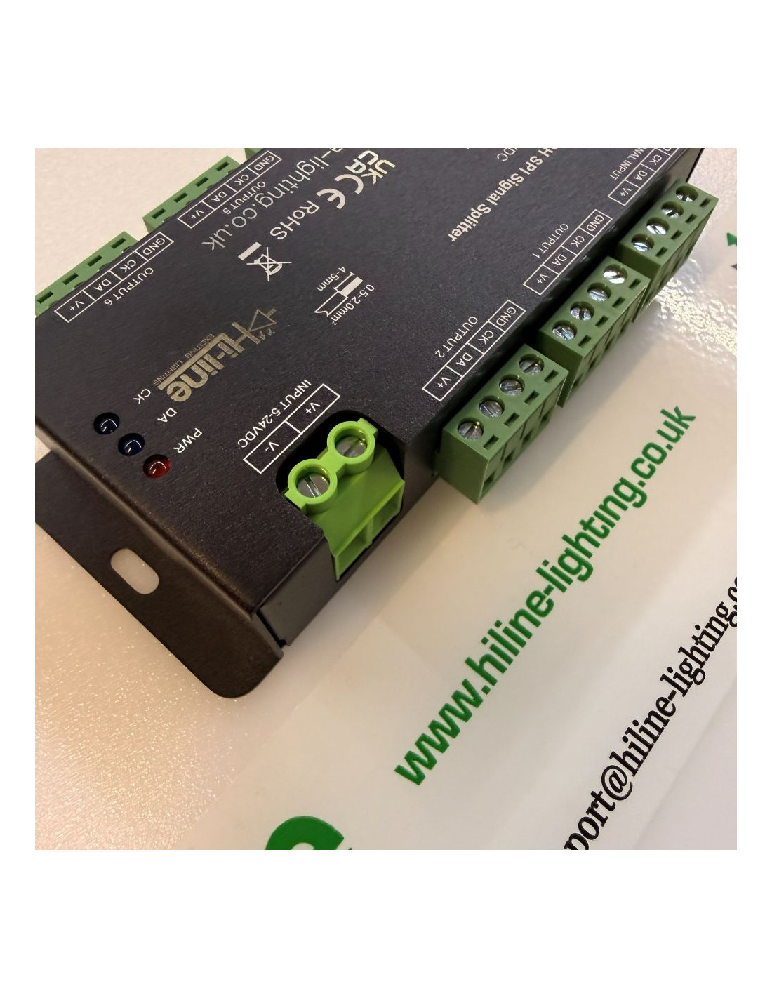
Status indicators
Built-in LEDs assist installation and fault finding:
-
Power indicator – confirms power present
-
DATA indicator – flashes when data is received
-
CLK indicator – flashes when clock signal is received (two-wire SPI)
Technical Specifications
Input signal: 1 × SPI (TTL)
Output signal: 6 × SPI (TTL)
Input voltage: 5–24V DC
Standby power: < 0.5W
Operating temperature: –20°C to +55°C
IP rating: IP20
Protection: Reverse polarity protection
Certifications: CE, EMC, LVD
Warranty: 5 Years
When to use this product
Use this splitter when you need:
-
Repeated pixel effects across multiple LED strip runs
-
Stable SPI signal distribution
-
Cleaner wiring and easier power management
-
Reliable architectural pixel installations
Do not use it when:
Installation disclaimer
Hi-Line Lighting supplies LED control components only.
All installations must be designed and carried out by qualified professionals in accordance with applicable regulations. Power calculations, cable sizing, grounding, and system design remain the responsibility of the installer.

